Try the Lotus 58. You get a bit more options over all.
For the those interested in a budget oriented, easily DIY built, 60% keyboard with USB C instead of the ‘standard’ TRRS cable.
New version fits existing plates (and 3D Designs) and have the same options for OLED & Encoders as before. Sandwich case plates are available in black & white, both with optional ears to tent/tilt.
Only thing to note is to check qmk docs if the screens controller is supported by default. If it is, it’s easy. If not it takes more work.
Yes you can. But you have to address the rgbs as a true matrix which is a fair bit more work.
I just used all my budget on prototypes. Sigh.
Cool thanks!
No, this is not asshole design. If the oil port was sticking further out, it’s gets knocked off if you lay the bike down. And then you have no oil at all, and a blown up motor.
It’s by good design the oil port is recessed. Yes it’s annoying to use a funnel, but it’s the preferable option.
Well the problem with that is when you lay the bike down, the oil port gets shaved off and you lose all your oil. Don’t ask me how I know.
So yeah, it’s a PITA to use a funnel, but it’s still the preferable option.
What am I missing, how is this done?
Lemmy.world was having mayor issues today, so not surprising if something broke.
Common core functionality:
- Hot-swap 4x12 Ortho
- RP2040, 4 MB flash
- USB type C
- Full per key RGB
- Optional encoders on all four corners
- Optional 1x2u & 2x2u layout
Option 1:
- North-facing keys
- Fits existing JJ40/BM40 cases
Option 2:
- South-facing keys
- Needs dedicated case design (possibly USB daughterboard)
Option 3:
- South-facing keys, compromise on the two top row keys by the USB connector.
- Fits existing JJ40/BM40 cases
Actually, I prefer liftoff
It should, at least as long as we are talking about choc switches on an MX spacing, or a dual footprint design, as the pin headers are spaced for that. Otherwise there will probably be interference, or very, very close to it at least.
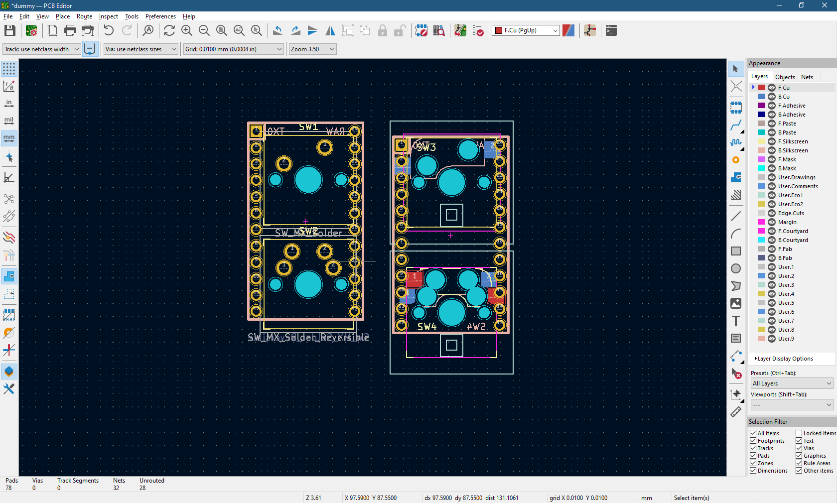
 How about this then? (No promises on signal integrity of that USB signal, we are pushing limits)
Just keep in mind, that placing the controller not at an edge, will likely make the USB port interfere with the next socket, it's not really meant for that. Meaning you should probably de-solder the port then. Also, by powering through the 5V/GND pins, you negate the VBUS detection, and there simply aren't enough pins/space to break that out as well, so it's a compromise.
I wasn’t planning on it since sacrifices two pins.
And seeing as the USB port is available to place by the edge very easily as you can place the controller over any key.
To explain, the USB port should end up needing only 3-5 mm edge on a sandwich case, or a hollow similar to how most pcb’s place it on a CNC/3d case.
Any particular reason beyond that? I’m open to reasonable compromises.
Btw, I can easily pull them out to a pair of pads, there is space for that.

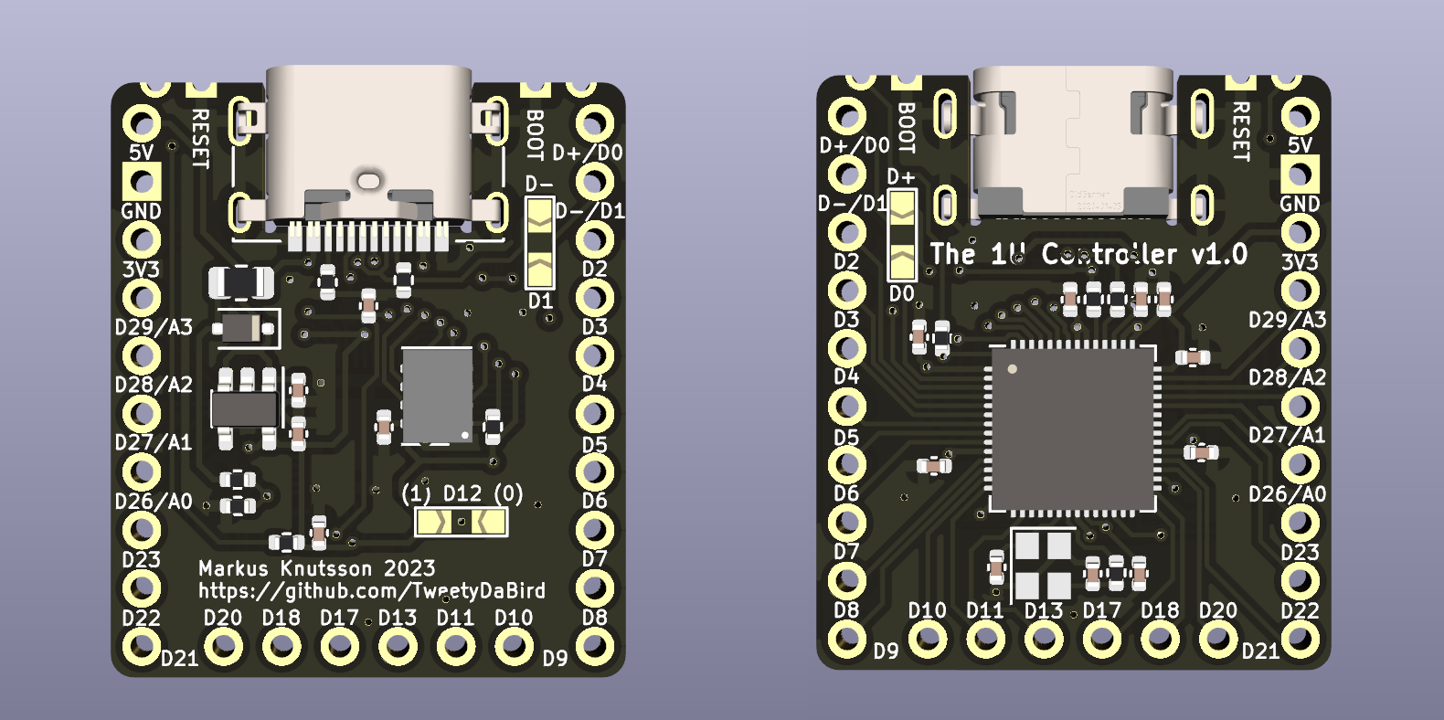
I guess an image says more than a thousand words?

Having always been somewhat annoyed I can't simply place a Pro Micro (or for that matter any other controller) over on top of a hot-swap socket without either turning it sideways, loosing pins, or some other creative solution.
So after trying to find other smaller controllers, but always ending up with a compromise, I finally got fed up with it, and started designing one of my own that is just large enough to fit the purpose.
RP2040 powered of course, and with a mid mount USB type C, the design is extremely low profile and fairly barebones with no status LED, no buttons, etc. making it easy and cheap to produce. And with 26 pin, there are 23 IO pins available for matrix and other things. VBUS detection for easy use with split keyboards, but beyond that stripped of anything fancy.
The boot/reset signals are available as castellated connections next to the USB, and only really meant for the first flashing/emergency flashing, as the rest would be handled by tapping a keycode to enter bootloader from within QMK/ZMK.
Edit: Added D+/- as jumpered breakouts on pins, se below. Also added a pin high/low for assigning sides on a split (useful for handwiring)
That’s not he projected range shown on the display. That’s the actual range the battery will give you.
They temporarily removed a bit of the safety margin built in to reduce battery wear, allowing people to get out of harms way without a stop to charge if they were on the limit. But only for people moving away from The affected area, etc. so smart and helpful.